Energy efficiency in
welding technology
The global discussions on climate change and the environment are increasingly calling the use of resources and energy consumption in production into question. "Sustainability," "life cycle assessment" and "energy efficiency" are terms used in these discussions that are particularly critical of production and manufacturing processes.
With this in mind, Peter Schmidt, Managing Director of SWISSBEAM AG, a leading Swiss specialist for electron beam welding, has written a technical paper which covers in detail the energy efficiency of all common joining processes used today. He then assesses the situation.
His analysis is based not only on the pure electrical performance data of the individual processes but also on several other parameters that influence the entire production process.
full technical article here (PDF)
One thing, in particular, is clear: based on the analytical criteria provided, electron beam welding performs significantly better than all other common fusion welding processes.
Overview of the most common
fusion welding processes:
Gas fusion welding
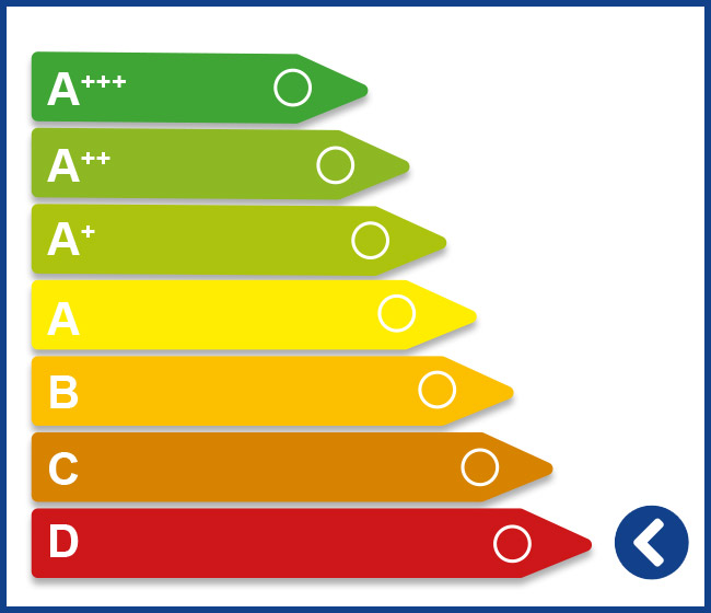
Gas fusion welding (also known as autogenous welding) is an old method still in use today. The metal is heated to the melting point with a torch flame. The required equipment consists of an acetylene and an oxygen cylinder with a mixing valve on the torch. The temperature of the flame is approx. 3200 °C. In most cases, a welding wire is used as filler material in this process. Due to a slow welding speed and considerable workpiece deformation caused by high heat effects, this process is becoming less and less desirable for cost and efficiency reasons.
Manual arc welding
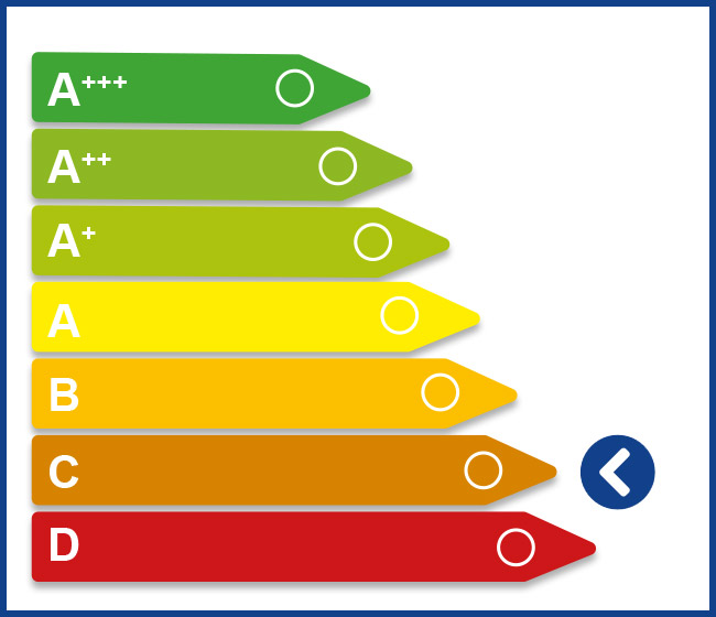
Manual arc welding (also known as electrode manual welding) is one of the oldest electrical welding processes for metallic materials and works by using the flow of an electrical current. The welding arc is several thousand degrees hot and acts as a heat source to melt the material at the joining zone. Depending on the process, there are melting and non-melting electrodes as well as free-burning and constricted arcs. The temperature of the arc is determined solely by the voltage and current. Therefore, arc welding processes can be controlled easily by regulating the voltage. However, in the ecological balance, manual electrode welding causes the greatest environmental damage due to the gases released. Welding devices for manual electric welding are relatively small and inexpensive.
Tungsten Inert Gas Welding (TIG)
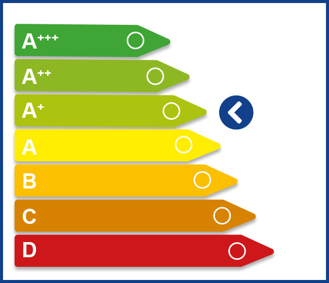
In TIG welding, an electric arc burns between the workpiece and a tungsten electrode. It requires a non-melting tungsten electrode and a gas (usually helium or argon) that prevents oxidation. A filler material in the form of a welding wire is often added for joining. The tungsten electrodes are available in different diameters and lengths and must be sharpened according to the type of current. In direct current welding, the electrodes are sharpened like pencils, whereas alternating current welding requires a rounded shape of the electrodes. TIG welding is a method that can be used to process almost any material that can be welded by fusion. It is suitable for almost all welds in root and constrained positions. TIG welding is much slower compared to other methods but produces excellent weld seams and makes it easy to control the weld pool. Therefore, this method is preferred for smaller and shorter welding points. As a disadvantage, it should be mentioned that TIG welding causes a considerable distortion of the component. Furthermore, the initial investment is higher compared to TIG/TAG welding, but this is also reflected in the quality achieved. TIG welding is considered to be a "clean" welding process that produces little welding fumes, which is why it is often undervalued. The process involves health risks that should not be underestimated: welders are exposed to a high degree of nitrogen oxides and ozone.
Inert gas metal arc welding (TIG/TAG)
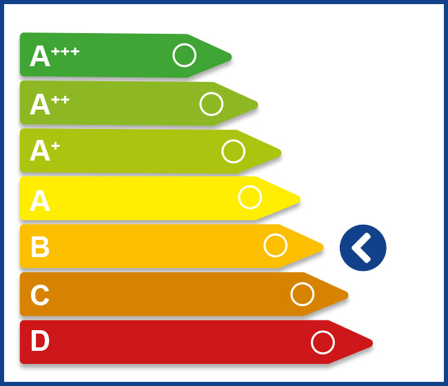
Inert gas metal arc welding (also known as inert gas welding) is an arc welding process which consists of TIG and TAG welding. With both methods, a melting welding wire is continuously fed at a variable speed. An additional gas is supplied to protect the materials from oxidation.
- TIG welding (metal welding with inert gases) usually uses argon or helium gas. The process is used for non-ferrous metals.
- TAG welding (metal welding with active gases) uses either a mixture of argon and nitrogen or just nitrogen. It is suitable for all ferrous metals.
Both methods allow for very long and regular welding seams and are suitable for more than just manual application. During robotic welding, spatter and clogged welding nozzles cause unstable processes and poor welding results, and the production process must be interrupted frequently in order to clean the nozzles from weld spatter. The energy efficiency here requires less spatter, a significantly higher welding speed and significantly improved gap bridging.
Orbital welding

Orbital welding is an automated TIG or MIG inert gas welding process in which the arc is mechanically guided without interruption all the way around a round body, i.e. by 360 degrees. The orbital welding process is primarily used in pipeline construction. The advantage of TIG orbital welding is the easy reproducibility. All welding sequences can be stored and repeated as often as necessary. Welding errors which may occur during a manual welding process can therefore be ruled out. A number of process parameters must be taken into account in addition to the correct inert gases in order to prevent impermissible pore formation. When using TIG orbital welding, the welding position changes continuously, and the weld pool is permanently exposed to the influence of gravity. The preparation of the seam is of particular importance here.
Plasma welding

Plasma welding uses a high-temperature gas mixture of helium and argon or argon and hydrogen, which protects the melt from oxidation and stabilizes the arc. The arc burns between a non-melting electrode and the material. The plasma beam used as a heat source is generated by the high energy supply, which transforms the inert gas into an electrically conductive state. Similar to TIG welding, the arc is formed between a non-melting tungsten electrode and the base material during plasma welding. However, unlike TIG welding, the arc is constricted by the welding torch construction using a water-cooled copper nozzle, which results in a comparatively higher power density. Plasma welding is suitable for all electrically conductive materials. It is widely used and covers, for example, applications in micro welding technology and pipeline construction.
Joint welding with plasma can be broken down into three process variants:
- Microplasma welding for the thinnest sheet thicknesses starting at 0.01 mm
- Plasma welding for sheet thicknesses between 1–3 mm
- Plasma keyhole welding up to approx. 8 mm in one layer
Keyhole requires costly preparation and complex technology. Almost all metals and their alloys are weldable, with the possibility of joining different materials.
Submerged arc welding

Submerged arc welding (UP welding) is an arc welding process with a melting wire or strip electrode. The arc and the weld pool are covered by a granular powder. This powderforms slag, which protects the welding zone from the influence of the atmosphere. The power coverhas a high thermal efficiency, which ledds to a high melting rate and therefore to a very high-quality result. The process is mainly used for welding long seams and thick sheets > 8 mm, primarily for industrial purposes. Disadvantages are the extensive seam preparation, the need for filler materials, the long welding time and the large amount of energy required. An alternative is the electron beam welding (EB) process.
Laser welding
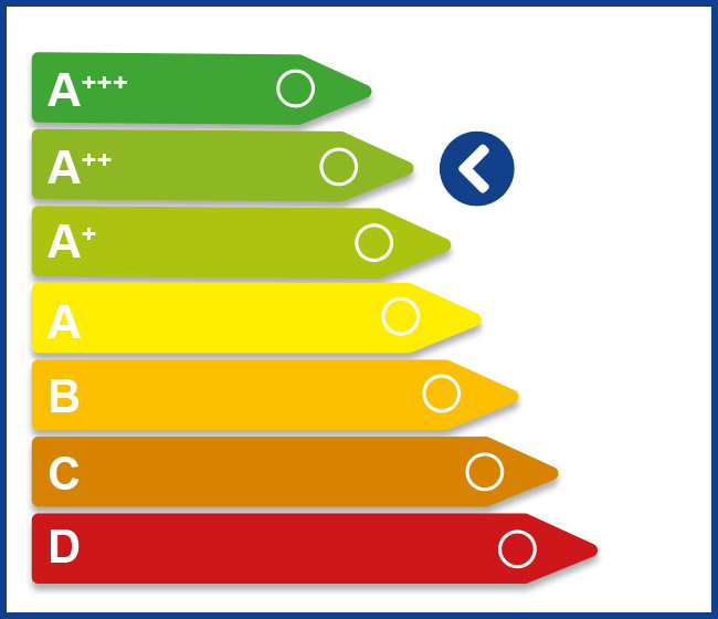
This process is mainly used for welding components with low welding depths. The laser beam is focused on the workpiece with the help of an optical system. Difficulties can arise when welding shiny materials, since copper is highly reflective of light, which makes it extremely difficult to melt the surface.
A large part of the laser power is absorbed by the shiny surface, which requires an increase in the energy used. This varies depending on the material and depends on the angle, temperature, polarization and wavelength. A significantly lower degree of absorption of copper compared to steel materials can be observed in the 1 μm wavelength range of a solid state laser. In addition, there is a critical zone of the copper area at the start of the welding process, which leads to strong fluctuations in the welding depth and low reproducibility of the welding result. In principle, a multi-beam bath technique is possible for a laser application, but it is technically complex, difficult and requires intensive maintenance. To protect the welding area from oxidation, it is constantly flushed with high-purity argon, which is heavier than air and therefore displaces oxygen. Added protection against radiation must be integrated, especially for laser welding. This is not necessary for other processes or is already provided by the vacuum chamber in the EB welding process.
Electron beam welding
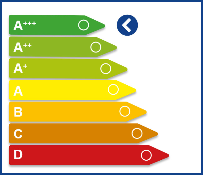
During the joining process of electron beam welding, electrons are released and accelerated or focused onto a small spot (diameter 0.1 mm) of the workpiece surface being welded by thermal emission in a high vacuum (< 10-4 mbar) in a triode system consisting of cathode, control electrode and anode. The electrons are projected onto the workpiece at a speed of about 2/3 of the speed of light, and a heat conversion takes place, which causes the material to melt. The electron beam has a much higher energy density than a laser beam and is also smaller. The welding process usually takes place in a vacuum, since the electron beam is absorbed by the air. This inhibits the production process when changing workpieces. The vacuum is best suited for the welding process, since there are no reactions between the workpiece melt and the air. Reactive materials such as titanium can be welded in a vacuum without the risk of oxidation at a much higher speed than, for example, in arc welding. When assessing overall productivity, the time required to evacuate the vacuum chamber must be taken into account.
With a high welding speed (up to 120 mm/sec.), narrow and thin joining seams can be introduced with very low thermal distortion. This results in extremely low shrinkage and distortion compared to the arc welding process and laser beam welding. Electron beam welding is usually carried out without the addition of a filler material and can be performed very easily with multi-beam bath technology. The high flexibility of this process makes it possible to weld thin foils of 0.1 mm up to very thick materials, such as steel with a welding depth of 100 mm, in a single work step. Difficult materials, high-melting or gas-sensitive material combinations. Magnetic materials must be demagnetized before welding; otherwise, the magnetic field could deflect the electron beam. The overall efficiency of the energy conversion process from input current to beam output power is significantly higher and more efficient than with laser welding. Resource efficiency and sustainability are clear indicators that are now regulated by the EU Eco-design Directive (2009/125/EC). Life-cycle assessment is a method of estimating the environmental impact of a product or process. These legal requirements are fulfilled with outstanding results in the electron beam welding process. Electron beam welding is characterized by an exceptionally high, reproducible quality of the welding results. This is also demonstrated by countless systems that were put into operation over 40 years ago and still perform reliably today.
© Fachzeitschrift „Schweisstechnik/Soudure 01/2020“ des SVS, Schweizerischer Verein für Schweißtechnik


